Measuring the Power Output of my SDRs ⚡
Paul Tagliamonte 2021-11-15 measurementOver the last few years, I’ve often wondered what the true power output of my SDRs are. It’s a question with a shocking amount of complexity in the response, due to a number of factors (mostly Frequency). The ranges given in spec sheets are often extremely vague, and if I’m being honest with myself, not incredibly helpful for being able to determine what specific filters and amplifiers I’ll need to get a clean signal transmitted.
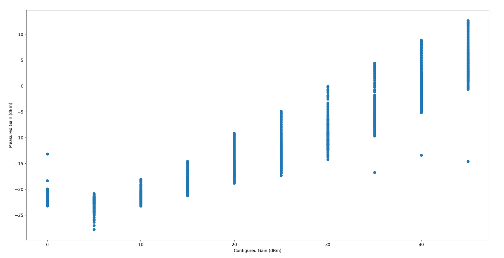
I was specifically interested in what gain output (in dBm) looks like across the frequency range – in particular, how variable the output dBm is when I change frequencies. The second question I had was understanding how linear the output gain is when adjusting the requested gain from the radio. Does a 2 dB increase on a HackRF API mean 2 dB of gain in dBm, no matter what the absolute value of the gain stage is?
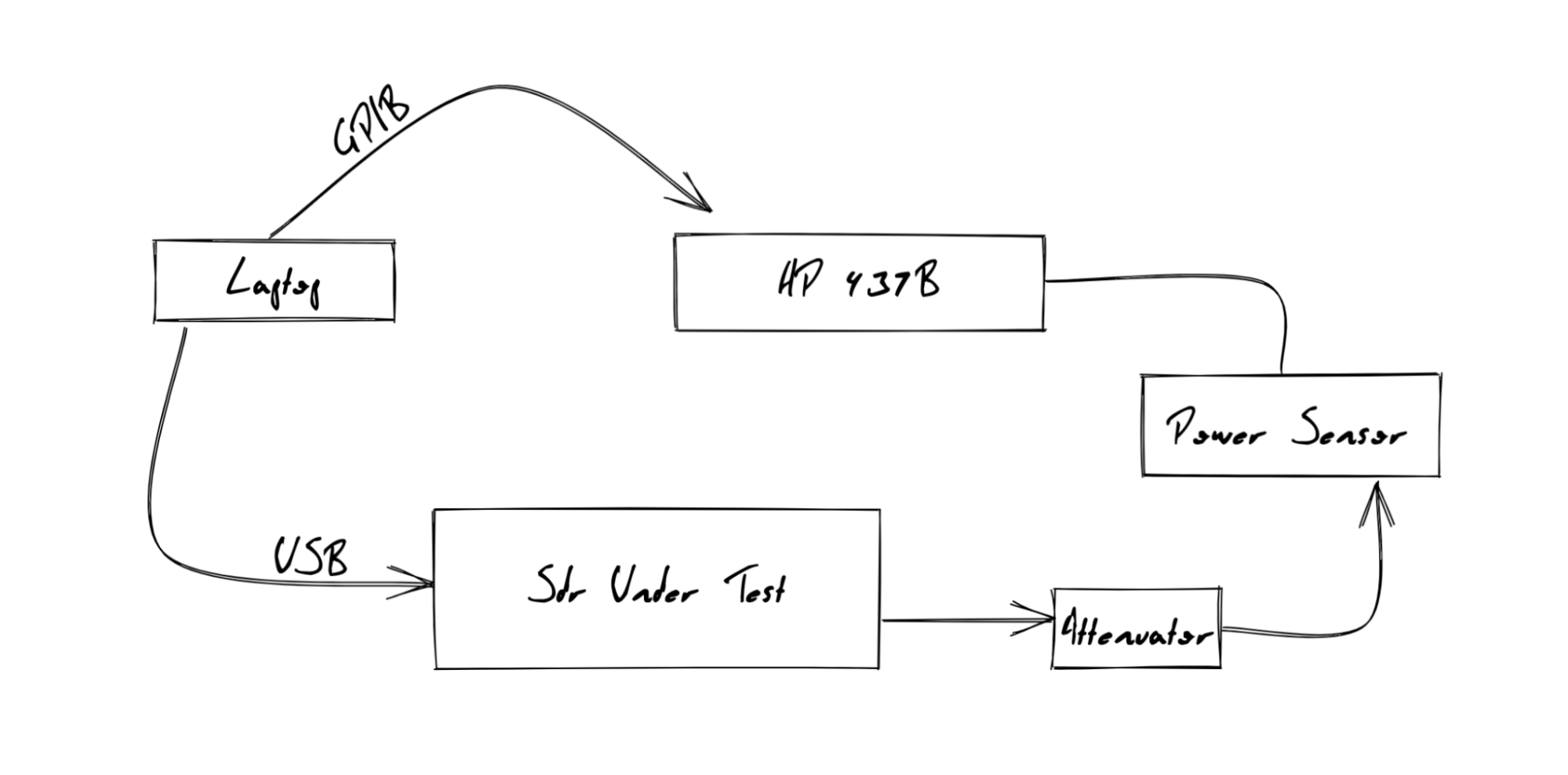
I’ve finally bit the bullet and undertaken work to characterize the hardware I do have, with some outdated laboratory equipment I found on eBay. Of course, if it’s worth doing, it’s worth overdoing, so I spent a bit of time automating a handful of components in order to collect the data that I need from my SDRs.
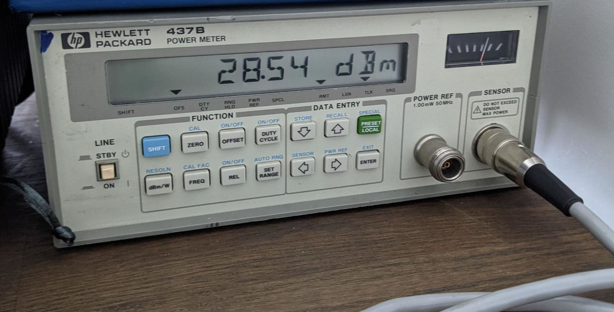
I bought an HP 437B, which is the cutting edge of 30 years ago, but still accurate to within 0.01dBm. I paired this Power Meter with an Agilent 8481A Power Sensor (-30 dBm to 20 dBm from 10MHz to 18GHz). For some of my radios, I was worried about exceeding the 20 dBm mark, so I used a 20db attenuator while I waited for a higher power power sensor. Finally, I was able to find a GPIB to USB interface, and get that interface working with the GPIB Kernel driver on my system.
With all that out of the way, I was able to write Go bindings to my HP 437B to allow for totally headless and automated control in sync with my SDR’s RF output. This allowed me to script the transmission of a sine wave at a controlled amplitude across a defined gain range and frequency range and read the Power Sensor’s measured dBm output to characterize the Gain across frequency and configured Gain.
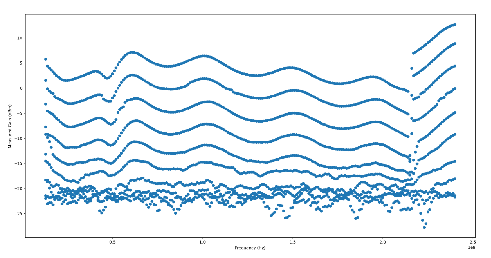
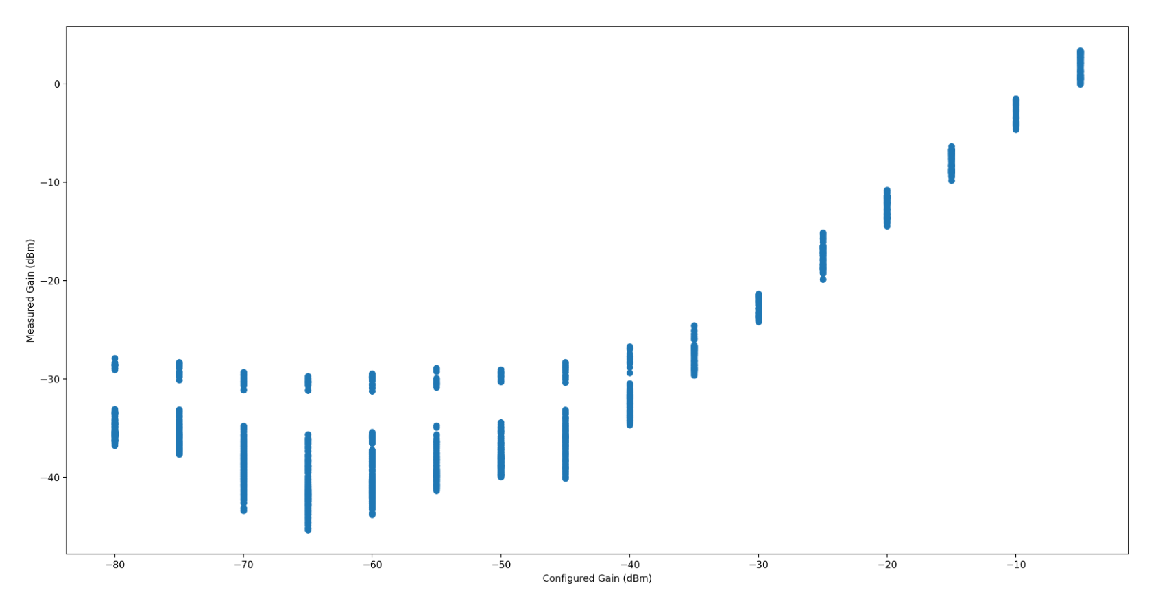
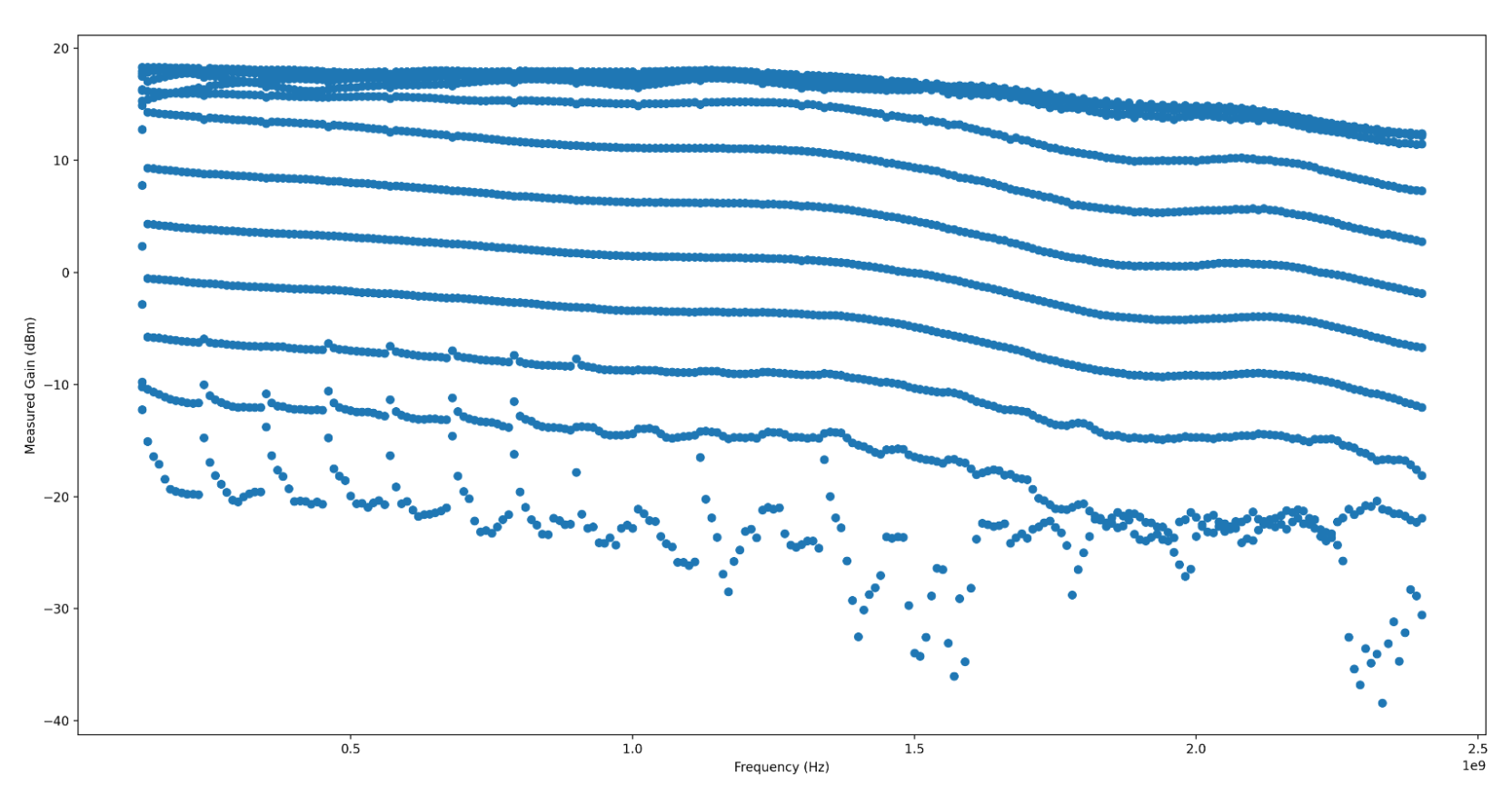
HackRF
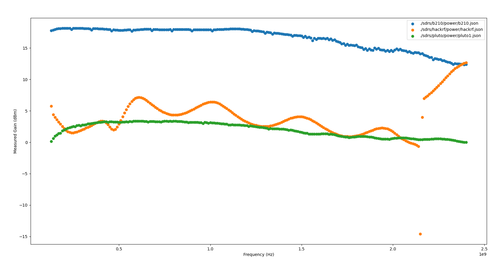
Looking at configured Gain against output power, the requested gain appears to have a fairly linear relation to the output signal power. The measured dBm ranged between the sensor noise floor to approx +13dBm. The average standard deviation of all tested gain values over the frequency range swept was +/-2dBm, with a minimum standard deviation of +/-0.8dBm, and a maximum of +/-3dBm.
When looking at output power over the frequency range swept, the HackRF contains a distinctive (and frankly jarring) ripple across the Frequency range, with a clearly visible jump in gain somewhere around 2.1GHz. I have no idea what is causing this massive jump in output gain, nor what is causing these distinctive ripples. I’d love to know more if anyone’s familiar with HackRF’s RF internals!
PlutoSDR
The power output is very linear when operating above -20dB TX channel gain, but can get quite erratic the lower the output power is configured. The PlutoSDR’s output power is directly related to the configured power level, and is generally predictable once a minimum power level is reached. The measured dBm ranged from the noise floor to 3.39 dBm, with an average standard deviation of +/-1.98 dBm, a minimum standard deviation of +/-0.91 dBm and a maximum standard deviation of +/-3.37 dBm.
Generally, the power output is quite stable, and looks to have very even and wideband gain control. There’s a few artifacts, which I have not confidently isolated to the SDR TX gain, noise (transmit artifacts such as intermodulation) or to my test setup. They appear fairly narrowband, so I’m not overly worried about them yet. If anyone has any ideas what this could be, I’d very much appreciate understanding why they exist!
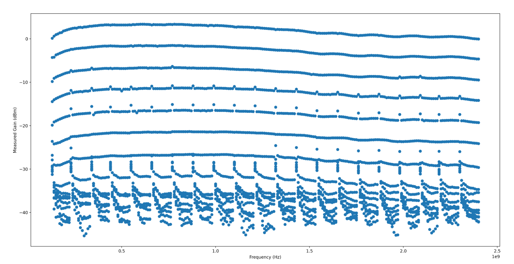
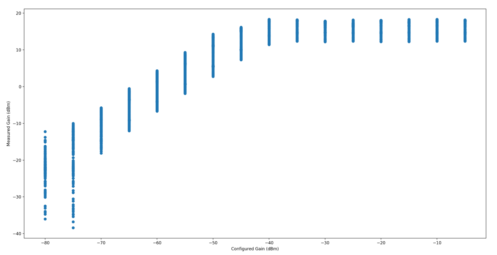
Ettus B210
The power output on the Ettus B210 is higher (in dBm) than any of my other radios, but it has a very odd quirk where the power becomes nonlinear somewhere around -55dB TX channel gain. After that point, adding gain has no effect on the measured signal output in dBm up to 0 dB gain. The measured dBm ranged from the noise floor to 18.31 dBm, with an average standard deviation of +/-2.60 dBm, a minimum of +/-1.39 dBm and a maximum of +/-5.82 dBm.
When the Gain is somewhere around the noise floor, the measured gain is incredibly erratic, which throws the maximum standard deviation significantly. I haven’t isolated that to my test setup or the radio itself. I’m inclined to believe it’s my test setup. The radio has a fairly even and wideband gain, and so long as you’re operating between -70dB to -55dB, fairly linear as well.
Summary
Of all my radios, the Ettus B210 has the highest output (in dBm) over the widest frequency range, but the HackRF is a close second, especially after the gain bump kicks in around 2.1GHz. The Pluto SDR feels the most predictable and consistent, but also a very low output, comparatively - right around 0 dBm.
| Name | Max dBm | stdev dBm | stdev min dBm | stdev max dBm |
|---|---|---|---|---|
| HackRF | +12.6 | +/-2.0 | +/-0.8 | +/-3.0 |
| PlutoSDR | +3.3 | +/-2.0 | +/-0.9 | +/-3.7 |
| B210 | +18.3 | +/-2.6 | +/-1.4 | +/-6.0 |