Reverse Engineering (another) Restaurant Pager system 🍽️
Paul Tagliamonte 2025-03-04 reverse-engineeringSome of you may remember that I recently felt a bit underwhelmed by the last pager I reverse engineered – the Retekess TD-158, mostly due to how intuitive their design decions were. It was pretty easy to jump to conclusions because they had made some pretty good decisions on how to do things.
I figured I’d spin the wheel again and try a new pager system – this time I
went for a SU-68G-10 pager, since I recognized the form factor as another
fairly common unit I’ve seen around town. Off to Amazon I went, bought a set,
and got to work trying to track down the FCC filings on this model. I
eventually found what seemed to be the right make/model, and it, once again,
indicated that this system should be operating in the 433 MHz ISM band likely
using OOK modulation. So, figured I’d start with the center of the band (again)
at 433.92 MHz, take a capture, test my luck, and was greeted with a now very
familiar sight.
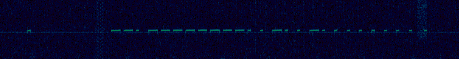
Same as the last goarounds, except the premable here is a 0 symbol followed
by 6-ish symbol durations of no data, followed by 25 bits of a packet. Careful
readers will observe 26 symbols above after the preamble – I did too! The last
0 in the screenshot above is not actually a part of the packet – rather,
it’s part of the next packet’s preamble. Each packet is packed in pretty tight.
By Hand Demodulation
Going off the same premise as last time, I figured i’d give it a manual demod and see what shakes out (again). This is now the third time i’ve run this play, so check out either of my prior two posts for a better written description of what’s going on here – I’ll skip all the details since i’d just be copy-pasting from those posts into here. Long story short, I demodulated a call for pager 1, call for pager 10, and a power off command.
| What | Bits |
| Call 1 | 1101111111100100100000000 |
| Call 10 | 1101111111100100010100000 |
| Off | 1101111111100111101101110 |
A few things jump out at me here – the first 14 bits are fixed (in my case,
11011111111001), which means some mix of preamble, system id, or other
system-wide constant. Additionally, The last 9 bits also look like they are our
pager – the 1 and 10 pager numbers (LSB bit order) jump right out
(100000000 and 010100000, respectively). That just leaves the two remaining
bits which look to be the “action” – 00 for a “Call”, and 11 for a “Power
off”. I don’t super love this since command has two bits rather than one, the
base station ID seems really long, and a 9-bit Pager ID is just weird. Also,
what is up with that power-off pager id? Weird. So, let’s go and see what we
can do to narrow down and confirm things by hand.
Testing bit flips
Rather than call it a day at that, I figure it’s worth a bit of diligence to make sure it’s all correct – so I figured we should try sending packets to my pagers and see how they react to different messages after flipping bits in parts of the packet.
I implemented a simple base station for the pagers using my Ettus B210mini, and
threw together a simple OOK modulator and transmitter program which allows me
to send specifically crafted test packets on frequency. Implementing the base
station is pretty straightforward, because of the modulation of the signal
(OOK), it’s mostly a matter of setting a buffer to 1 and 0 for where the
carrier signal is on or off timed to the sample rate, and sending that off to
the radio. If you’re interested in a more detailed writeup on the steps
involved, there’s a bit more in my christmas tree post.
First off, I’d like to check the base id. I want to know if all the bits in what I’m calling the “base id” are truly part of the base station ID, or perhaps they have some other purpose (version, preamble?). I wound up following a three-step process for every base station id:
- Starting with an unmodified call packet for the pager under test:
- Flip the Nth bit, and transmit the call. See if the pager reacts.
- Hold “SET”, and pair the pager with the new packet.
- Transmit the call. See if the pager reacts.
- After re-setting the ID, transmit the call with the physical base station, see if the pager reacts.
- Starting with an unmodified off packet for the pager system
- Flip the Nth bit, transmit the off, see if the pager reacts.
What wound up happening is that changing any bit in the first 14 bits meant that the packet no longer worked with any pager until it was re-paired, at which point it begun to work again. This likely means the first 14 bits are part of the base station ID – and not static between base stations, or some constant like a version or something. All bits appear to be used.
I repeated the same process with the “command” bits, and found that only 11
and 00 caused the pagers to react for the pager ids i’ve tried.
I repeated this process one last time with the “pager id” bits this time, and
found the last bit in the packet isn’t part of the pager ID, and can be either
a 1 or a 0 and still cause the pager to react as if it were a 0. This means
that the last bit is unknown but it has no impact on either a power off or
call, and all messages sent by my base station always have a 0 set. It’s not
clear if this is used by anything – likely not since setting a bit there
doesn’t result in any change of behavior I can see yet.
Final Packet Structure
After playing around with flipping bits and testing, the final structure I was able to come up with based on behavior I was able to observe from transmitting hand-crafted packets and watching pagers buzz:
Commands
The command section bit comes in two flavors – either a “call” or an “off”
command.
| Type | Id (2 bits) | Description |
| Call | 00 | Call the pager identified by the id in pager id |
| Off | 11 | Request pagers power off, pager id is always 10110111 |
As for the actual RF PHY characteristics, here’s my best guesses at what’s going on with them:
| What | Description |
| Center Frequency | 433.92 MHz |
| Modulation | OOK |
| Symbol Duration | 1300us |
| Bits | 25 |
| Preamble | 325us of carrier, followed by 8800us of no carrier |
I’m not 100% on the timings, but they appear to be close enough to work reliabily. Same with the center frequency, it’s roughly right but there may be a slight difference i’m missing.
Lingering Questions
This was all generally pretty understandable – another system that had some good decisions, and wasn’t too bad to reverse engineer. This was a bit more fun to do, since there was a bit more ambiguity here, but still not crazy. At least this one was a bit more ambiguous that needed a bit of followup to confirm things, which made it a bit more fun.
I am left with a few questions, though – which I’m kinda interested in understanding, but I’ll likely need a lot more data and/or original source:
Why is the “command” two bits here? This was a bit tough to understand because of the number of bits they have at their disposal – given the one last bit at the end of the packet that doesn’t seem to do anything, there’s no reason this couldn’t have been a 16 bit base station id, and an 8 bit pager id along with a single bit command (call or off).
When sending an “off” – why is power off that bit pattern? Other pager IDs
don’t seem to work with “off”, so it has some meaning, but I’m not sure what
that is. You press and hold 9 on the physical base station, but the code winds
up coming out to 0xED, 237 or maybe -19 if it’s signed. I can’t quite
figure out why it’s this value. Are there other codes?
Finally – what’s up with the last bit? Why is it 25 bits and not 24? It must take more work to process something that isn’t 8 bit aligned – and all for something that’s not being used!